For this project, I set out to create a dummy load that could handle HF at 100 watts for a reasonable amount of time. Until taking on this project, I was using the 20 watt dummy load kit from QRP-Labs. This worked fine for my QMX+, but not well for my Yaesu FT-710.
I first looked on the QRZ.com swapmeet page, but failed to find a good dummy load for a reasonable price. That is when i started investigating a homebrew solution. I considered a “cantenna” type dummy load, however I wanted mine to be more compact.
I saw online that many operators were using a single 100-150 watt 50Ω resistor on a heatsink (or sometimes just an aluminum box). The theory behind my design, which uses 4 resistors, was to physically spread out the heat across a larger heatsink to make heat transfer more efficient. This led me to selecting 4 x 200Ω 35 watt resistors in parallel.
With this arrangement, I was able to get a 50Ω non-inductive load with a max power rating of approximately 140 watts. With the resistors being in an TO-220 package, I was able to mount them directly to a heatsink with a single fastener.
To hold the resistors and coaxial connector, I decided to design a custom PCB. This is not entirely necessary, as the whole thing could be make with perf board and/or wires. However, by using a custom PCB, I was able to keep the connections as short as possible while maintaining a small form factor.
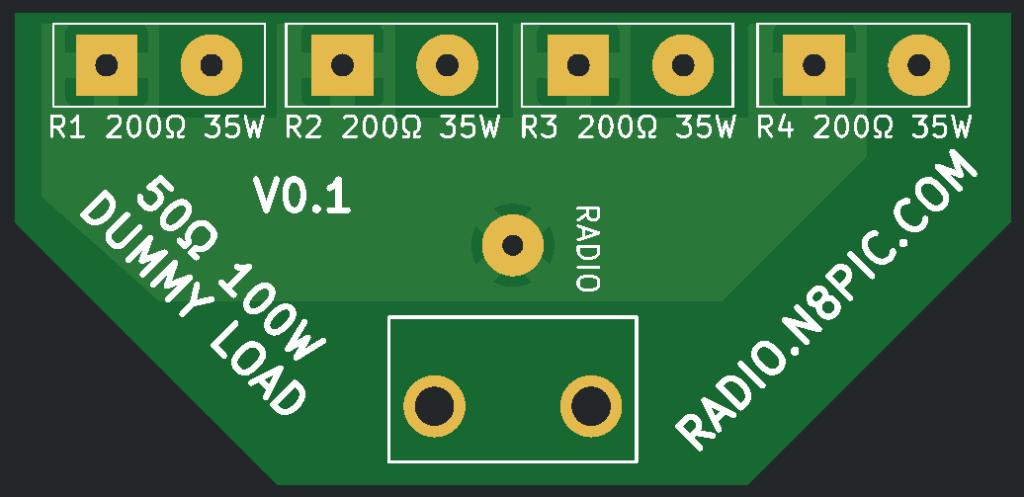
Because I wanted every component to be PCB mountable, I chose to use a BNC connector. This is less common than SO-239 or N-type for HF radio, however BNC adapter cables are easy to obtain, and I even had a few on hand.
I chose to orient the resistors in an alternating pattern to spread the heat out as much as possible.
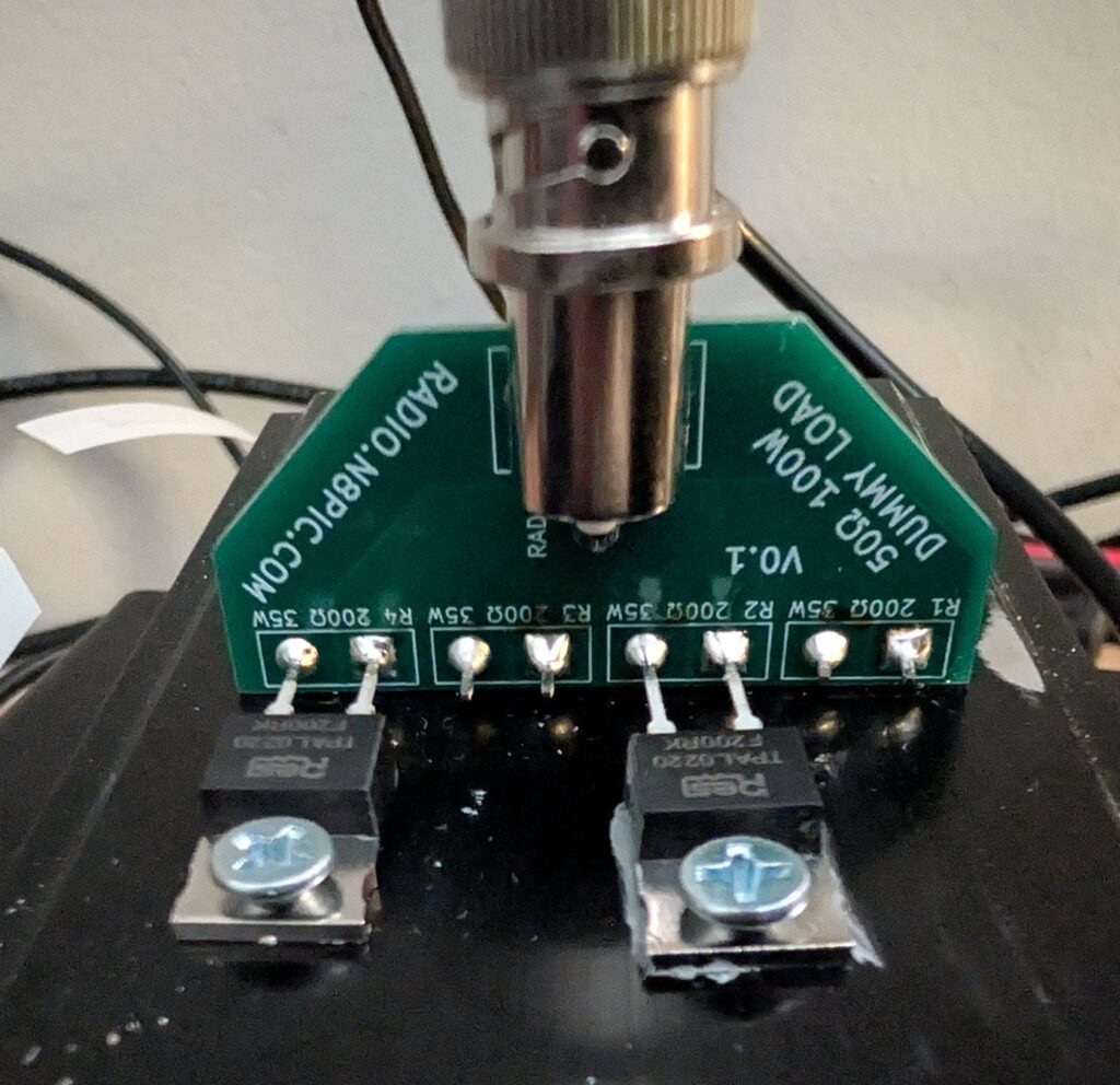
Before soldering anything, I laid out the resistors with the legs sticking through the PCB holes on the back of the heatsink and marked the hole locations. Then, I drilled and tapped the 4 holes for 6-32 screws. Next, I arranged the resistors and PCB the same as before, but I screwed down the resistors in position.
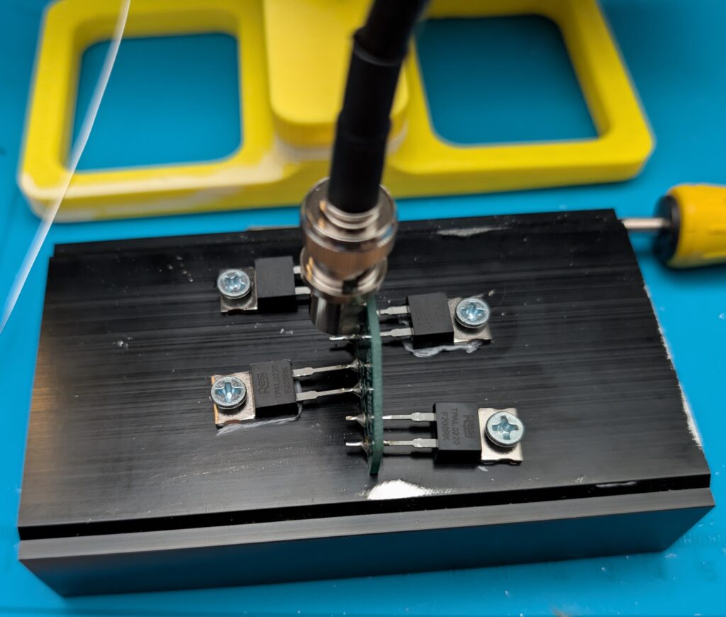
With everything in its place, I soldered the resistors to the PCB while still attached to the heatsink. After this, I removed the assembly from the heatsink and soldered the BNC connector onto the board.
Finally, I applied regular CPU thermal paste to the back of each resistor. Screwing the resistors back into the heatsink allowed the thermal paste to spread evenly under the heat spreaders.
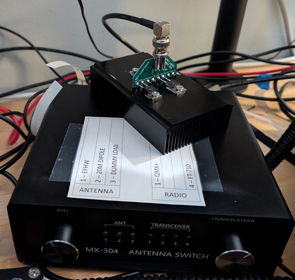
This is the dummy load completed, sitting on top of my antenna switch. When transmitting 100 watts CW into the dummy load, the resistors get to hot to touch in about 10-15 seconds. The heatsink warms up a noticeable amount in the next 30 seconds or so.
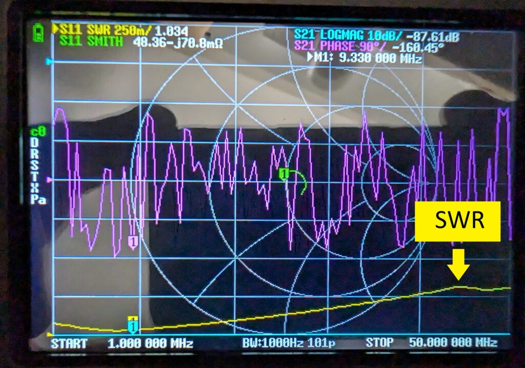
On the network analyzer, you can see that the SWR for 160m-6m (1.8MHz – 50MHz) is less than 1.3:1. This is ideal for a ham radio HF dummy load. The SWR is over 3:1 for the 2m band (~144MHz) and over 10:1 for the 70cm band (~440MHz), making this not ideal for VHF and UHF radios. Different high-frequency resistors would need to be selected for VHF/UHF.
I did some testing to see how much the temperature increased at different power levels. Below are my results.
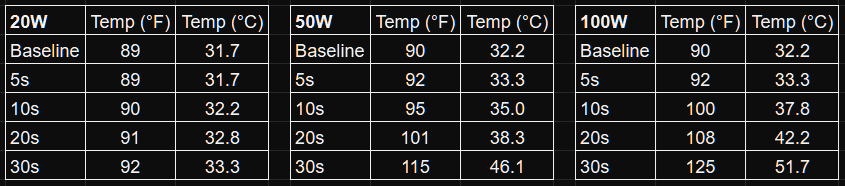
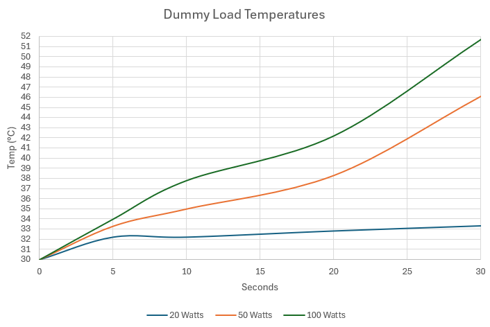
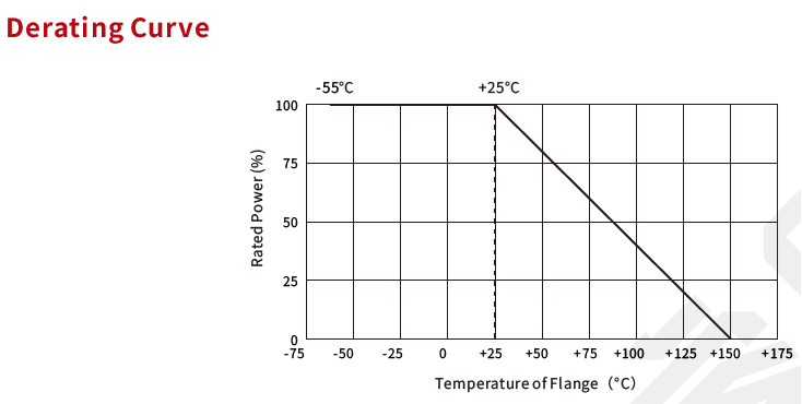
Temperatures were taken using a laser thermometer after transmitting a CW tone. Operating range of the resistors is 150°C maximum. At the highest temperature measured (51°C), the resistors are still rated over 100W total. That said, a larger heatsink would allow the dummy load to take high power for longer.
PARTS
Resistors and BNC Connector: https://www.digikey.com/en/mylists/list/84QDW6XPYY
Heatsink: https://a.co/d/ieLHmKH
Total Cost: ~35 USD