This is intended to be a summary of my QMX+ build with some notes, suggestions, and solutions I may have found.
The QMX+ is a 6m-160m CW/Digital transceiver from QRP-Labs.com. I purchased this as a kit, but you can also pay around $60 USD to have it assembled for you, although you’ll have to wait a while for it.
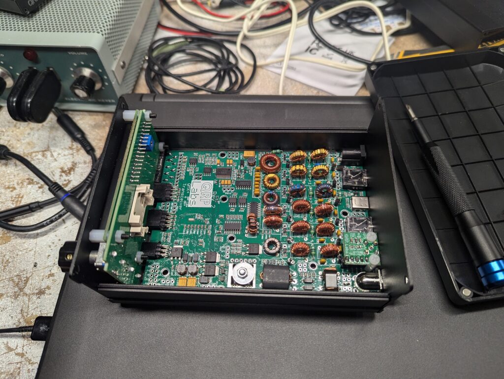
Construction is fairly straight forward, especially if you have built one of the other QRP-Labs radios (I have previously built a QDX and a QCX-mini). It mostly consists of inserting through-hole components, winding some inductors and transformers, and a lot of careful soldering.
I HIGHLY recommend reading the manual multiple times while you’re waiting for your kit to arrive. A little confidence goes a long way.
One thing Hans notes is that there is much more ground plane on this board due to its size and that it’s 6 layers. Turn up your soldering iron, use some lower temperature solder (i.e. leaded solder), and be very patient. The ground connections will take a lot of heat.
I found it particularly tedious to get all 19 inductors and 2 transformers soldered well. My approach was to secure each one in place with solder first, and then go back after with a multi-meter and perfect each connection. There must be continuity between each end (or ends) of the inductors. The assembly guide also gives you test points to confirm proper installation of the larger transformer (T501).
For the trifilar toroid, leave the legs as long as you can, and tin the very tips of the ends so you can find continuity between the sets of wires. Now the tinned ends probably wont fit through the holes, so cut off the tinned parts, and there should still be enough wire to get through the holes and soldered properly.
I also found that coiling the wires for the trifilar toroid and the larger transformer (T501) was easier to do by hand. I used a small clamp in a vice to hold one end, and another clamp to hold my end. Keeping a bit of tension allowed for an even winding without the need for a power drill. It takes barely any extra time, and there is no risk of over-winding or breaking it.
I highly recommend using the serial terminal to confirm operation before securing the side panels. Plug in a USB cable, connect a dummy load, and supply 12V power. You can access the terminal through PUTTY. Under “Hardware Tests”, there is a diagnostic tool. Go through each band and confirm that you are getting at least some power on each of the bands (use +/- to change the band, and hold “t” to test).
I found that I was getting 3.5-5W on most of the bands, with the exception of 0.5W on 10m and 1.0W on 6m! Similarly to the power fix on the 20/30m QCX transceivers, I found that spreading out the windings evenly on the LPF toroids for those bands brought the power up a bit. Now I was up to 1.5W on both 10m and 6m. Spreading out the windings lowers the inductance, so the next step if that doesn’t bring up the power enough is to remove windings from the toroids. Start with the LPF toroid closest to T501 (L517 for 10m). Heat the pad back up, remove one leg of the inductor, and use a solder sucker or wick to remove the solder from the hole (if you don’t have either of those or you are having trouble, just solder the leg of the inductor to the top side of the board).
Do this method one turn at a time on each of the inductors and test using the diagnostic tool in the serial terminal after every change. Only change 1 thing at a time!
In all, I would rate this build as “advanced”. If you are new to soldering or electronics in general, I would suggest building a QDX, QCX+, or even an ATU-100 as your first foray into kit building.
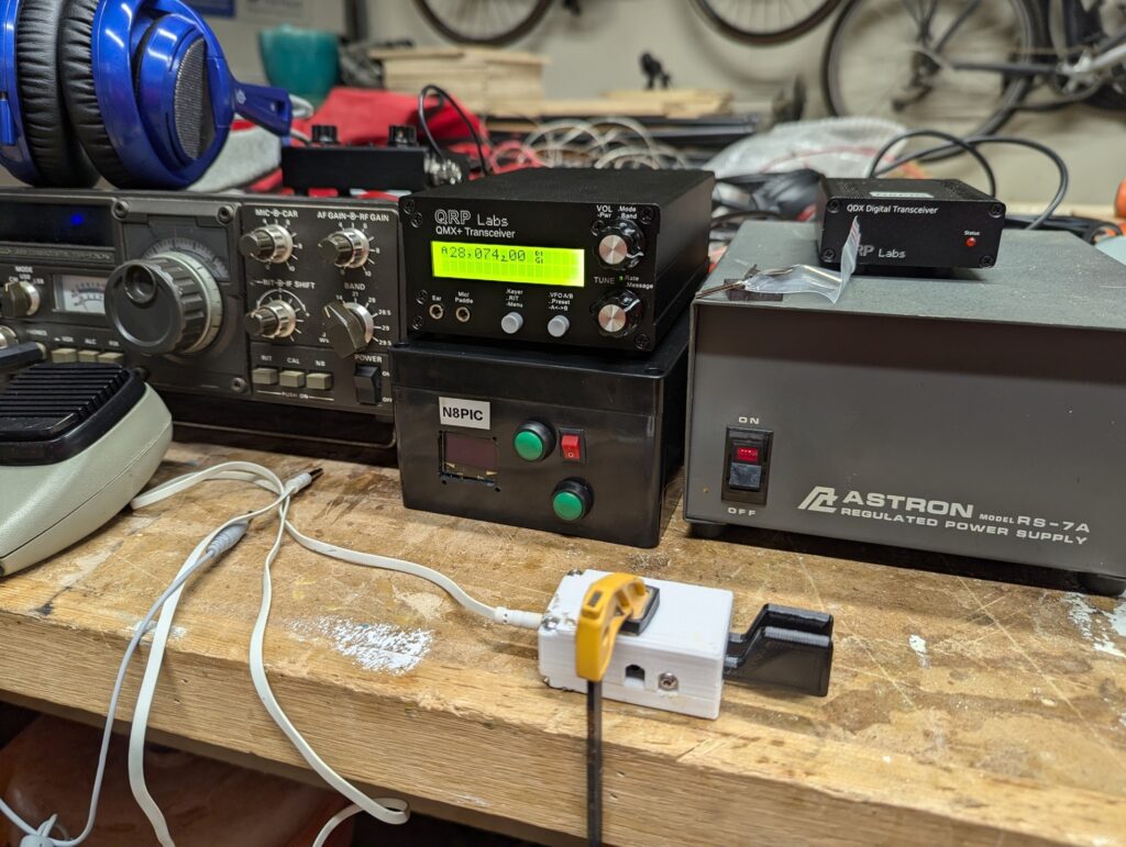
My new QRP-Labs QMX+ next to my Kenwood TS-120V, antenna tuner, QDX, and power supply.